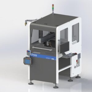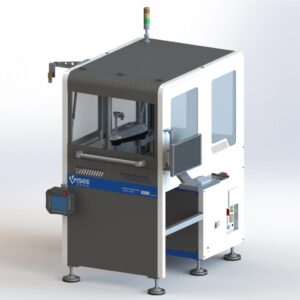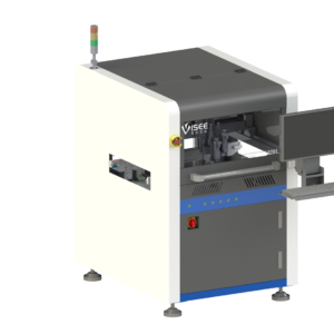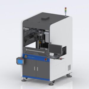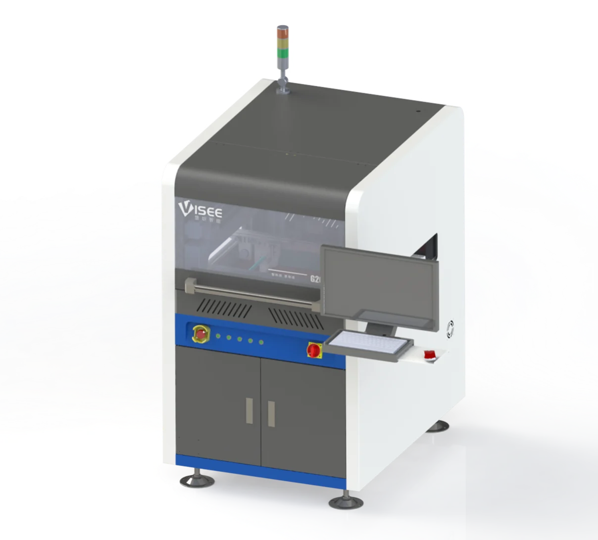
Product Overview
A 3-axis Cartesian dispensing system for inline rail-conveyor integration. Image-based programming and vision positioning support material application on PCB assemblies, with the valve and process configuration selected around the material and deposit requirements.
Suitable Applications
- Underfill around compatible component packages
- Chip or lead encapsulation and surface sealing
- Dam-and-fill and selected PoP assembly processes
- Red adhesive, solder paste or silver paste dispensing after material and valve evaluation
Key Features
Vision-guided programming
A small field of view combined with image fusion supports board positioning and image-based path definition. Review fiducial visibility, component access and fixture repeatability for your assembly.
Valve selection around the material
The equipment documentation lists piezoelectric, precision screw and pneumatic jetting valves. Material viscosity, filler particles, pot life and required deposit geometry determine the suitable valve and process settings.
Line and process integration
The documented platform includes tool calibration, board recognition and production statistics. Confirm the required upstream/downstream handshake and MES data scope during the configuration review.
Technical Specifications
| Parameter | Documented configuration / value |
|---|---|
| Motion configuration | 3-axis Cartesian |
| Installation | Inline rail conveyor integration |
| Dispensing travel (X × Y × Z) | 500 × 400 × 50 mm |
| PCB thickness | 0.5–7 mm |
| Conveyor width adjustment | 50–400 mm |
| Conveyor height | 900 ±50 mm |
| Conveyor load capacity | 3 kg |
| Vision camera | 6 MP industrial color camera |
| Programming | Image-based |
| Line interfaces | SMEMA / HERMES; confirm project implementation |
| Valve choices | Piezoelectric, precision screw or pneumatic jetting; configuration dependent |
| Dimensions (L × W × H) | 910 × 1300 × 1843 mm |
| Weight | 650 kg |
| Power supply | AC 220 V, 10 A, 50 Hz |
| Air supply | 0.4–1 MPa |
| Control platform | Ubuntu 18.04 LTS, 64-bit listed in supplied documentation; confirm delivered software version |
Air-pressure range updated to 0.4–1 MPa from the confirmed JCX specification.
Base Configuration and Options
The documented base configuration is a 3-axis Cartesian platform with image-based programming and a 6 MP camera. Confirm the exact valve, software and interface scope in the quotation.
- Pressure booster pump and microbalance
- Barcode reader and laser height measurement
- Bottom return conveyor or dual-lane transport
- Dual-valve mechanism
- 2D deposit checks or 3D bead-profile inspection
Installation and Project Inputs
Prepare the conveyor-height and board-support requirements, AC power, compressed air and access for maintenance. Use the confirmed 0.4–1 MPa supply range and verify air quality requirements. Check material handling, ventilation and curing requirements against the selected material.
Product Documents
Download the three-page English selection brief with specifications, configuration choices and project preparation information.
Frequently Asked Questions
Can one valve dispense every adhesive?
No. Material compatibility and deposit requirements must be evaluated. The listed valve types are configuration choices, not a guarantee that every material can be processed by one setup.
Are 2D and 3D adhesive inspection included?
They are listed as optional equipment. Include the required defect types and acceptance criteria in your quotation request.
Applications and Project Support
Industry Applications
Process Guides
These application routes support equipment discussion. The selected material, process or inspection task still requires a configuration review.