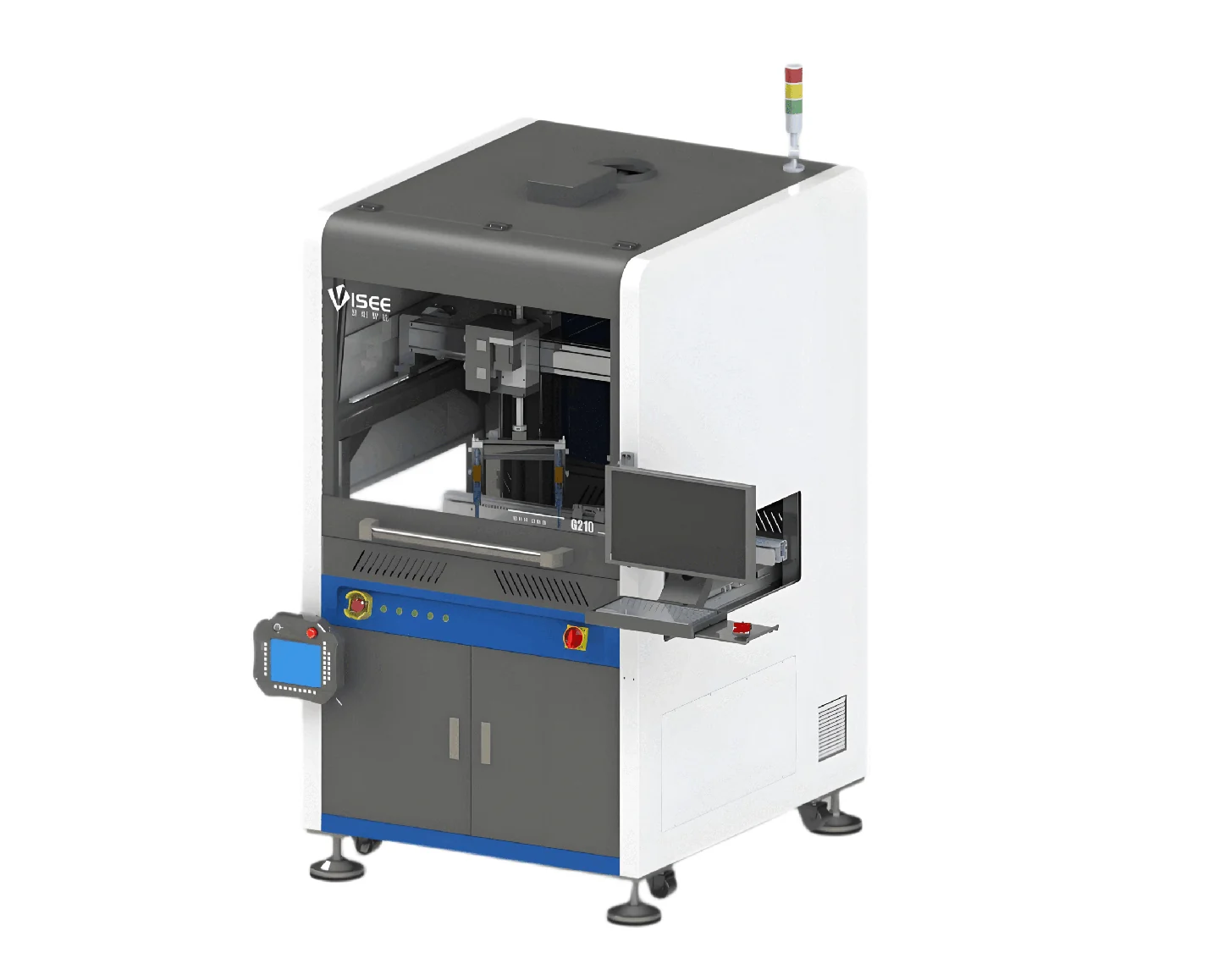


Product Overview
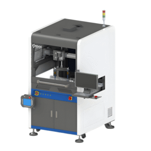
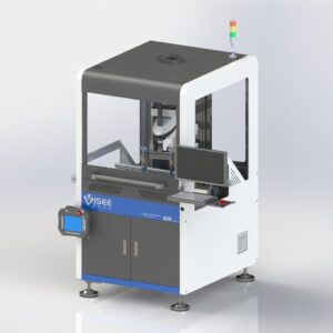
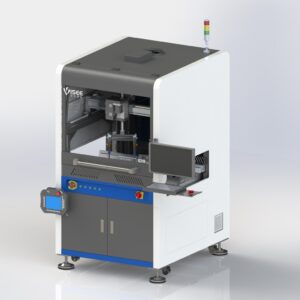
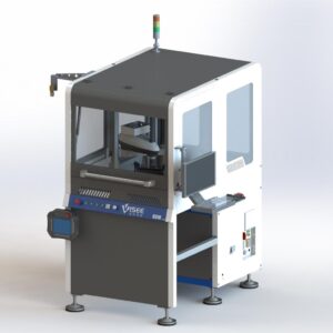
A family of 3-axis inline coating configurations with panoramic vision and image-based programming. Choose the valve arrangement and coating travel for the board layout, component access and keep-out areas instead of treating all F3 variants as the same machine.
Suitable Applications
- Selective coating of PCB assemblies with defined keep-out zones
- Mixed PCB production with program-based changeover
- Protective coating processes for control boards and power electronics after material qualification
Key Features
Panoramic board positioning
Feature-matching vision locates the board and supports image-based path definition. Board features, fixtures and coating boundaries should be included in the application review.
Choose the correct F3 variant
The base F3 uses two valves in line. F3A offers adjustable dual-valve spacing; F3B and F3C use four-valve layouts. Their available travel differs, so select the variant against the actual coating path.
Connect production information
The documentation lists board identification, program selection and production statistics. Network protocols and customized MES integration should be specified as part of the delivered configuration.
Technical Specifications
| Parameter | Documented configuration / value |
|---|---|
| Motion configuration | 3-axis |
| Installation | Inline rail conveyor integration |
| F3 coating travel (X × Y × Z) | 450 × 450 × 100 mm |
| F3A / F3B coating travel | 200 × 450 × 100 mm |
| F3C coating travel | 200 × 440 × 100 mm |
| F3 valve arrangement | Two valves in line |
| F3A valve arrangement | Adjustable dual-valve spacing |
| F3B valve arrangement | Four valves in line; tilt optional |
| F3C valve arrangement | Four valves, front/rear arrangement; front-valve tilt optional |
| Documented component clearance | 90 mm above and below conveyor plane; verify fixture and valve access |
| PCB edge clearance | ≥4 mm |
| Coating width per pass | 2–30 mm, dependent on valve |
| Conveyor height | 900 ±40 mm |
| Conveyor speed | 2–13 m/min |
| Vision camera / lens | 20 MP industrial camera / 16 mm FA lens |
| Programming | Image-based and offline |
| Power supply | AC 220 V, 10 A, 50 Hz |
| Compressed air | 0.4–0.7 MPa |
| Exhaust requirement | 15 m³/min in supplied documentation; confirm installation specification |
| Approximate weight | 650 kg |
| Repeatability | ±0.02 mm; confirm test conditions |
Repeatability is specified as ±0.02 mm with the unit confirmed by JCX; agree the measurement and acceptance conditions.
Base Configuration and Options
The F3 family uses 3-axis motion and panoramic vision. Valve arrangements and usable travel are specific to F3, F3A, F3B and F3C; the ordered variant must be stated explicitly.
- Post-coating image storage
- Barcode reading
- Bottom return conveyor
- Coating presence/absence inspection
- Tilt mechanisms on the applicable four-valve configurations
- Customized MES and production-data integration
Installation and Project Inputs
Plan extraction, compressed air, power and material handling before installation. Confirm the machine envelope for the selected variant and ensure adequate clearance for loading, cleaning and maintenance. Define coating thickness, keep-out boundaries and curing conditions through application evaluation.
Product Documents
Download the three-page English selection brief with specifications, configuration choices and project preparation information.
Frequently Asked Questions
Does every F3 variant offer 450 × 450 mm travel?
No. That travel is listed for the base F3. F3A and F3B list 200 × 450 mm, while F3C lists 200 × 440 mm, each with 100 mm Z travel.
Is coating inspection included?
Coating presence/absence inspection is listed as an option. Confirm the required detection scope; it should not be assumed to provide full thickness or defect measurement.
Applications and Project Support
Industry Applications
Process Guides
These application routes support equipment discussion. The selected material, process or inspection task still requires a configuration review.