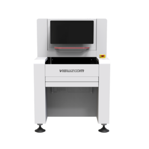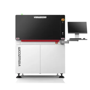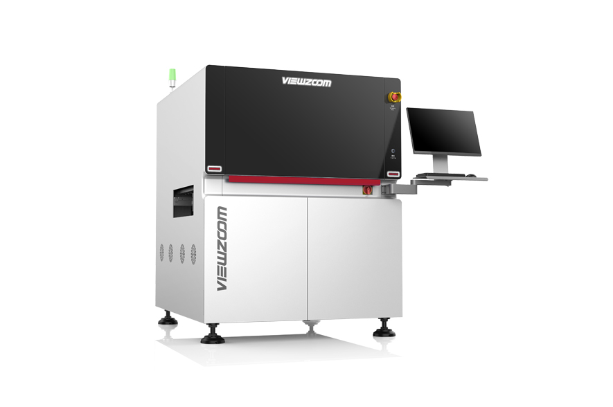

Product Overview
A single-track 2D automated optical inspection configuration for boards up to 510 × 510 mm. RGB, coaxial and white lighting support visible assembly inspection, with camera and software options selected for the required inspection tasks.
Suitable Applications
- Visible component-placement and solder-joint inspection
- Review of offset, tombstoning and visible solder defects after programming
- Single-track PCB production where a 510 × 510 mm board envelope is required
Key Features
Lighting for visible inspection
RGB surrounding light, coaxial light and white light provide different illumination approaches. Inspection recipes should be evaluated against reflective surfaces, component markings and the relevant defect examples.
Program-controlled transport
The single-track conveyor includes software-controlled width adjustment. The source describes three-stage stopping, with boards longer than 220 mm automatically changing to a single-stage process.
Connect inspection and review
Barcode recognition and SMEMA are listed in the equipment features. Review stations, MES connection, offline programming and SPC analysis are listed as options rather than assumed standard deliverables.
Technical Specifications
| Parameter | Documented configuration / value |
|---|---|
| Transport | Single track; fixed front track |
| PCB size range (L × W) | 50 × 50 to 510 × 510 mm |
| Maximum PCB thickness | 6 mm |
| Main camera | 12 MP standard; 21 MP optional |
| Camera resolution | 12 µm standard; 15 / 7 µm optional |
| Lighting | RGB surrounding + coaxial + white light |
| Transport clearance | Top 50 mm / bottom 50 mm |
| PCB bending adjustment | ±4 mm |
| Line interface | SMEMA |
| Dimensions (L × W × H) | 1000 × 1250 × 1600 mm |
| Weight | 1100 kg |
| Power supply | AC 200–240 V, 50/60 Hz |
| Power consumption | 1.2 kW standard / 3 kW maximum |
| Compressed air | 0.5 MPa, 5 L/min |
| Control platform | Windows 10 listed in source documentation; confirm delivered software version |
Package-size claims depend on the selected resolution. Confirm defect coverage through samples and an agreed acceptance procedure.
Base Configuration and Options
The listed configuration includes single-track transport, 12 MP imaging, 12 µm resolution and SMEMA. The delivered software and inspection scope should be confirmed in the specification.
- 21 MP camera or alternative camera resolution
- Repair / review workstation
- MES connection and SPC analysis
- Offline programming and centralized judgment
- Automatic changeover and labeling configurations
Installation and Project Inputs
Provide board dimensions, component information, inspection criteria and sample images or boards. Confirm conveyor height and flow direction, AC power, compressed air, network requirements and space for any selected review workstation.
Product Documents
Download the three-page English selection brief with specifications, configuration choices and project preparation information.
Frequently Asked Questions
Should I choose Isee 510 or Isee 510D?
The 510 is a single-track configuration. The 510D has a dual-track arrangement with different listed board-width conditions; compare those limits against your line before selecting.
Are MES and SPC included as standard?
They are listed in the optional-equipment section of the source documentation. Confirm the required software modules and integration scope.
Applications and Project Support
Industry Applications
These application routes support equipment discussion. The selected material, process or inspection task still requires a configuration review.