Product Overview
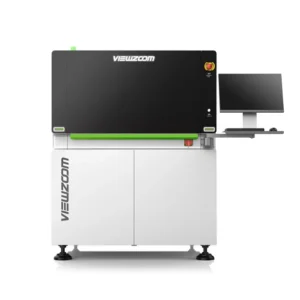
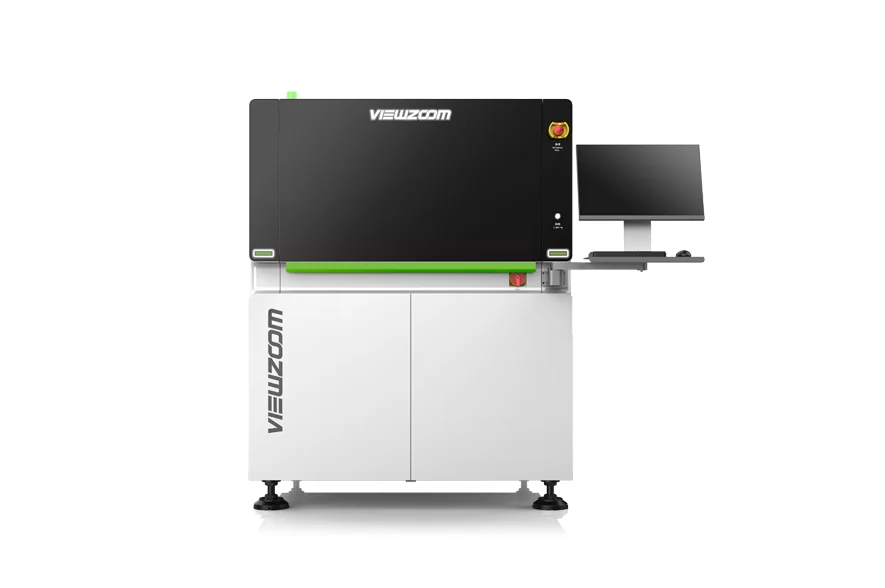
A single-track 3D solder paste inspection configuration for use after printing and before placement. The system measures paste height, area and volume, with recipe limits established for the stencil, pad design and printing process.
Suitable Applications
- Solder paste checks after stencil printing
- Review of insufficient, excessive, missing or offset deposits
- Process monitoring based on paste measurement results
Key Features
Measure paste before assembly
The documented inspection items include height, area, volume, displacement and shape. Use these measurements to evaluate the printing process before components are placed.
Set limits around the print process
The source lists checks for insufficient or excessive paste, missing printing, offset, bridging and shape defects. Inspection limits should be established against the actual pad, stencil and paste process.
Select optics and transport
The listed system uses a 5 MP camera, two 3D projectors and a single-track conveyor. Camera resolution and board-handling requirements should be confirmed for fine-pitch or mixed-product work.
Technical Specifications
| Parameter | Documented configuration / value |
|---|---|
| Transport | Single track; fixed front track |
| PCB size range (L × W) | 50 × 50 to 510 × 510 mm |
| Maximum PCB thickness / weight | 6 mm / 5 kg |
| Inspection items | Height, area, volume, displacement and shape |
| Main camera | 5 MP high-speed camera |
| Camera resolution | 15 µm standard; 12 / 7 µm optional |
| 3D projectors | 2 |
| Documented paste inspection height | 700 µm; source also lists Z-axis lift to 25 mm |
| Minimum measurable deposit | 80 × 80 µm, subject to application validation |
| Minimum deposit spacing | 80 µm, subject to application validation |
| Transport clearance | Top 50 mm / bottom 50 mm |
| PCB bending adjustment | ±4 mm |
| Dimensions (L × W × H) | 1100 × 1450 × 1600 mm |
| Weight | 1100 kg |
| Power consumption | 500 W standard / 800 W maximum |
| Compressed air | 0.5 MPa, 10 L/min |
| Control platform | Windows 10 listed in source documentation; confirm delivered software version |
The source lists repeatability figures without a full test method. They are not used here as a guaranteed production capability.
Base Configuration and Options
The listed measurement configuration uses a 5 MP camera, 15 µm resolution and two 3D projectors. Measurement performance must be evaluated under the applicable setup and test conditions.
- 12 µm or 7 µm camera-resolution alternatives
- Review the required data interface and software scope with JCX; do not assume MES or closed-loop control is included
Installation and Project Inputs
Confirm the electrical supply in the installation specification, together with compressed air, conveyor height, flow direction and data outputs. Provide stencil and pad information, paste type, sample boards and the intended acceptance limits.
Product Documents
Download the three-page English selection brief with specifications, configuration choices and project preparation information.
Frequently Asked Questions
Does SPI replace post-reflow AOI?
No. SPI examines paste deposits before placement, while post-reflow AOI checks visible assembled components and solder joints. They address different stages of the process.
Is a 25 mm Z-axis lift a 25 mm paste measurement range?
No. The source lists a 700 µm paste inspection height separately from the Z-axis lift. Confirm the required measurement range for your application.
Applications and Project Support
Industry Applications
These application routes support equipment discussion. The selected material, process or inspection task still requires a configuration review.